

My first robot
Objectives
Build a robot that:
- Runs on a tracked chassis
- Has a tilt and pan camera
- Controlled by a Raspberry Pi Zero
- Can be controlled through a website
Components
- Dagu Rover 5 tracked chassis
- MotoZero motor controller
- Tilt and pan camera mount with servos
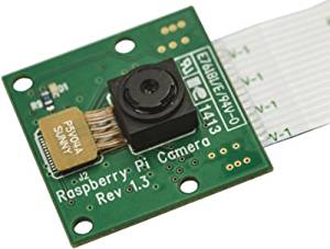
- Raspberry Pi camera
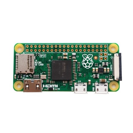
- Raspberry Pi Zero computer
- 40-pin 2x20 HAT Dual Male Headers
- Stacking Header for Raspberry Pi - 2x20 Extra Tall Header
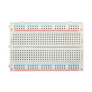
- Solderless Plug-in Breadboard
-
Selection of solid core wires:
- Female connectors on both ends
- Female connector on one end
- No connectors
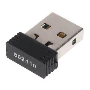
- USB wireless dongle
- Micro USB to USB adaptor
- USB battery to power Raspbrry Pi Zero
-
6 AA rechargeable batteries to power:
- Motors on Rover 5
- LEDs on encoders on Rover 5 motors
- Servos on pan and tilt mount
Dagu Rover 5 tracked chassis
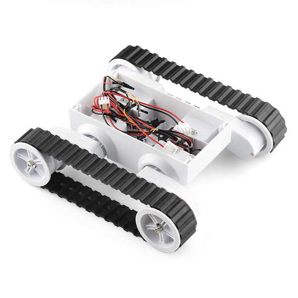
There are several versions of the Rover 5. They may have 2 or 4 motors. The motors may be supplied with or without quadrature encoders.
Chasis
Specification
- Adjutable ground clearance. Varies by 1.5"
- 9.5" long, 9" wide, and 3" tall in its default, flattened configuration
Motors
The specifications are:
- Brushed DC motors
- 210 mA free run at 7.2V (assumed for 2 motors)
- Stall curent 2.4A at 7.2V (assumed for 2 motors)
- 86.8:1 gearboxes
- Speeds as high as 10 in/s (25 cm/s) (assumed for 2 motors)
- Weight: 1.6 lb (0.72 kg) (assumed for 2 motors)
The wiring is:
- Red - positive
- Black - negative
Quadrature Encoders
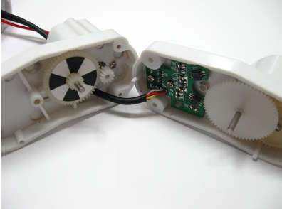
The encoder consist of:
- LED
- Light sensor
- Disc divided into black and white quadrants
The encoders specification is:
- LED requires 5V
- One sensor channel for black quadrants ?
- One sensor channel for white quadrants ?
- resolution of 1000 counts per three revolutions of the wheel, or 333.33 CPR (counting both rising and falling edges of both encoder channels)
The wiring is:
- Red - positive
- Black - negative
- White - channel A ?
- Yellow - Channel B ?
MotoZero motor controller
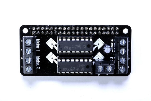
The MotoZero motor controller is designed to match the form factor of the Raspberry Pi Zero and attaches directly onto the GPIO connector. Normally this would make all the unused pins on the GPIO inaccessible for other uses, but since it comes as a kit, you can put an extra tall or "stacking" header on it that will allow access to these pins.
The motor controller can drive 4 motors forwards or backwards using an external power source and controlled using 12 GPIO pins on the Raspberry Pi Zero.
The specification is:
- 2x Motor driver chips each with 2 H-bridge circuits
- Control 4 motors independently in both forwards and reverse
- Built-in flyback diodes within the controller chips, which prevent damage from motor 'flyback' voltage spikes
Tilt and pan camera mount with servos
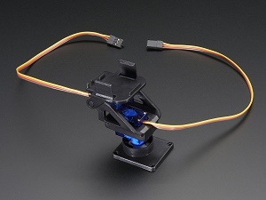
Servos
The servo will move a motor to a specific position in reponse to a signal. The signal must be a square wave with a high value lasting between 1ms and 2ms sent with 20ms between the start of each pulse i.e. 50Hz. A 1ms pusle will move the motor to the bottom of its range. A 2ms pulse will move the motor to the top its range. Pulse lengths in between will move the motor to other values in the range.
TowerPro SG90 Servo specification:
- Torque: 4.8V: 25.00 oz-in (1.80 kg-cm)
- Speed: 4.8V: 0.12 sec/60°
- Pulse Width: 500-2400 µs (seen differing figures)
- Both the power and the pulse signal should be 4.8V
The wiring is:
- Red - postive
- Brown - negative
- Yellow - signal
Raspberry Pi Zero
Raspberry Pi Camera
Headers
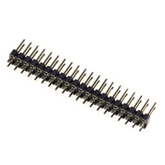
Solder to Raspberry Pi Zero
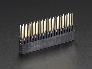
Solder to MotoZero motor controller
Breadboard
USB wireless dongle
Batteries
There are several types of AA batteries:
| Technology | Voltage | Rechargeable |
| Zinc-carbon | 1.5V | No |
| Alkaline | 1.5V | No |
| Nickel-Cadmium | 1.2V | Yes |
| Nickel-metal hydride | 1.2V | Yes |
Rechargeable batteries are usually used for robot projects:
- To save money in the long term
- To provide the high current needed by motors
This is why some of the specifications above are for 7.2V (6 X 1.2V) or 4.8V (4 X 1.2V). We can also draw off a subset of 4 of the batteris to 4.8V which should be enough for the encoders on the motors and the servos on the pan and tilt mount.
Software
Operating System
Download "Rasbian Jessie with Pixel" i.e. with graphical desktop from Rasberry Pi website
After downloading the .zip file, unzip it to get the image file (.img) for writing to your SD card.
On Windows 10 use Win32DiskImager to copy .img file to micro SD card
Configuring wireless ntwork
Append these lines to /etc/wpa_supplicant/wpa_supplicant.conf
network={
    ssid="your_network_name"
    psk="your_network_password"
    proto=RSN
    key_mgmt=WPA-PSK
    pairwise=CCMP
    auth_alg=OPEN
}
raspi-config
Use sudo rasp-config to:
- Expand filesystem to use the whole microSD card
- Change password for the pi user
- Change the boot option to desktop GUI, requiring user to login
- Change the hostname using "Advanced Options"
Fixing the IP address of the Raspbery Pi
By default the IP address of on the Raspberry Pi is dynamically allocatec by your network router. This is controlled by these lines in /etc/network/interfaces
iface eth0 inet dhcp
iface wlan0 inet dhcp
You can find the wireless gateway using this command e.g. 192.168.1.254
sudo route -nee
For the robot project I will only be using a wireless network connection. So I changed the wireless network line to this.
iface wlan0 inet static
address 192.168.1.xxx
netmask 255.255.255.0
gateway 192.168.1.254
where xxx is the fixed IP address on the wireless network
The GPIO pins
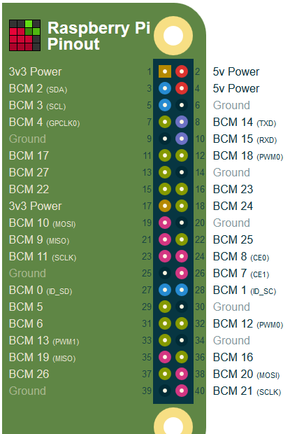
The cost of the Raspberry Pi Zero has been kept to a minimum - just £4!! One way this has been done is not to include the 2X20 header for the GPIO pins. If you need to use the GPIO pins, a I do for this project, you need buy the header for £1 and solder it on.
The ground, 3.3V and 5V pins are easily tested with a multimeter. Testing the GPIO that will be used to control the motors etc. will require turning them on from the Rasberry Pi. This can done like this:
#!/bin/bash
gpio=$1
count=$2
echo $gpio >/sys/class/gpio/export
echo out >/sys/class/gpio/gpio$gpio/direction
while [ $count -gt 0 ];
do
  echo 1  >/sys/class/gpio/gpio$gpio/value
  sleep 1
  echo 0  >/sys/class/gpio/gpio$gpio/value
  sleep 1
done
echo $gpio >/sys/class/gpio/unexport